
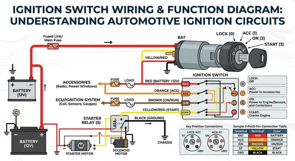
Reading an Ignition Switch Wiring Diagram
Pull an ignition switch out of the dash and you’ll usually find four or five wires bundled together, none of them labeled, all roughly the same gauge. Guess wrong on even one connection and you can end up with a car that won’t start, a starter that stays engaged too long, or accessories that stay powered after you pull the key. A wiring diagram exists to take the guessing out of that job — it maps exactly which wire does what, so you connect each one to the terminal it’s supposed to reach.
What the Diagram Is Actually Showing You
At its core, an ignition switch diagram traces five connections: power in from the battery, power out to the starter motor, power to accessories like the radio and wipers, power to the ignition system itself, and a ground path back to the chassis. Manufacturers label these terminals with a fairly consistent shorthand — BATT, START, ACC, IGN, and GND — and once you can read those five labels, most ignition wiring starts to make sense regardless of the vehicle.
| Terminal | What It Powers |
|---|---|
| BATT | Constant power from the battery |
| ACC | Accessories (radio, wipers, dash lights) |
| IGN | Ignition system and fuel pump |
| START | Starter motor (only during cranking) |
| GND | Return path to the chassis |
Not Every Diagram Looks the Same
The style of diagram you’re working from usually falls into one of three categories, and it’s worth knowing which one you have before you start.
A basic wiring diagram just shows the connections as simple lines between components — no color coding, minimal detail. It’s fine for a straightforward job but easy to misread if the wiring in your actual vehicle has been modified.
A color-coded diagram matches each wire’s diagram color to the actual wire color in the harness, which removes most of the ambiguity for anyone who isn’t already familiar with the vehicle. This is the version worth tracking down if you can find one for your specific model.
A factory service diagram is the most detailed of the three and the one professional shops rely on — it includes splice points, fuse locations, and often the resistance values you’d expect to read across each terminal with a multimeter. It takes longer to parse but leaves the least room for error.
Working Through It Without Damaging Anything
Disconnect the battery before you touch a single wire. This one step prevents the two most common accidents in this job: a short across the starter circuit, and a shock from a live accessory wire.
Confirm the diagram actually matches your vehicle’s year and model before relying on it. Manufacturers change wiring layouts between model years more often than people expect, and a diagram that’s one year off can send you down a false trail.
Trace one wire at a time, starting with BATT since it’s the easiest to confirm — it should read battery voltage with the key off. Work outward from there rather than trying to identify all five wires at once.
Take a photo of the original wiring before you disconnect anything. However well you think you’ll remember the layout, a photo settles any dispute during reassembly.
Label each wire as you disconnect it. A strip of tape and a marker is enough — this alone prevents most of the mistakes that happen during reinstallation.
Where This Job Usually Goes Wrong
The most common failure is using a diagram for the wrong model year, since even small trim or engine differences can shift the wiring layout. The second is skipping the battery disconnect — a step that feels optional right up until a wire touches something it shouldn’t. The third is relying on wire color alone: aftermarket harnesses and past repairs sometimes don’t follow factory color conventions, so the diagram’s terminal labels matter more than the colors do when the two disagree.
The Bottom Line
An ignition switch only has five real connections, but getting even one wrong can leave you with a car that won’t start or an accessory circuit that never shuts off. A diagram matched to your exact vehicle, a disconnected battery, and a labeled wire for every connection you pull apart will get you through this cleanly — most of the actual failures come from skipping one of those three, not from the wiring itself being complicated.
A couple of things people usually want to know:
The START terminal is only ever live for the few seconds you’re cranking the engine — if it’s staying powered longer than that, the switch itself (not the wiring) is usually the problem. And if a diagram and the actual wire colors disagree, trust the terminal labels on the diagram over the colors, since re-wires and aftermarket harnesses don’t always follow the original color code.